Sarah Smith, Global Market Manager, Analytical Equipment, Bal Seal Engineering Inc, California, USA
This article examines the changing landscape of supercritical fluid chromatography (SFC) testing and what it means for OEMs as they develop the next generation of SFC equipment. In particular, it focuses on ensuring optimal seal design within pumps that are used in an SFC system.
When supercritical fluid chromatography (SFC) was introduced in 1962, it focused primarily on testing the decaffeination of coffee and tea. It was also used to test flavours, fragrances, pesticides and pharmaceuticals.
Since 2012, there has been an upsurge in the repurposing of SFC to meet the increasing need for cannabinoid testing in states that have legalised cannabis for medicinal or recreational use (see ‘The Regulatory Push’). SFC’s popularity is attributed to a number of factors. Besides the low viscosity of supercritical fluids, it offers limited thermal degradation and uses recyclable, eco-friendly solvents that produce a non-toxic residue (with the exception of GCO2 and LCO2).
The result of this surge in popularity is an increased demand for SFC equipment that offers even higher throughput and higher resolution for testing cannabinoids.
Why SFC?
Whilst liquid chromatography (LC) and gas chromatography (GC) can be used to perform the required separation on cannabinoid samples, SFC has become the preferred method for both chiral and achiral compounds because of its favourable operating conditions.
Typical LC solvents are acetyl nitrile (ACN), methanol buffer (MeOH) and water with formic acid (H2O + 0.1% FA), all of which are toxic aggressive media that are costly and difficult to dispose of.
By contrast, the solvents for SFC are recyclable. SFC follows principles similar to those of LC, but uses carbon dioxide (CO2) as the primary mobile phase and ethanol, methanol, or isopropyl alcohol (IPA) as the co-solvent to extract or separate compounds. SFC is ideal for testing the potency of delta-9-tetrahydrocannibinol (THC), as well as tetrahydrocannabinolic acid (THCA), cannabidiol (CBD), cannabidiolic acid (CBDA) and cannabinol (CBN). It is also good for the analysis of complex mixtures comprised of analytes, which may range in polarity. [1] SFC separates samples efficiently at lower temperatures and limits thermal degradation.
Although a number of possible eluents can be used in SFC as the mobile phase, CO2 is preferred. A key advantage with SFC is that the CO2 mobile phase allows for quick recycling at laboratories – eliminating the costs associated with solvent disposal. CO2 is mostly odourless, non-flammable, and colourless, and it is an existing method for plant concentration extraction.[2] In addition, CO2 is typically a by-product of other chemical reactions and releases no new chemicals into the environment.
Because of the inability of CO2 to elute polar or ionic compounds, adding a co-solvent (methanol, for example) or a modified fluid improves the solvating ability of the supercritical fluid which, in turn, enhances the separation selectivity.
The regulatory push
In late 2012, in the USA, Colorado and Washington approved recreational marijuana use, which drove governmental regulation for retail sales.[3]
Testing requirements were established for all concentrates of delta-9-tetrahydrocannibinol (THC). Because there is no federal oversight to monitor quality or safety, each state has taken responsibility for setting its own testing guidelines.
Whilst there is minimal synchronicity between the states, some states, including Colorado, quickly embraced supercritical fluid chromatography as the primary method for THC potency testing. By early 2014, Colorado began setting government standards on marijuana potency and acceptable testing results to be communicated to consumers. Many small start-up labs popped up virtually overnight to provide needed testing services.
Supercritical fluid
The main difference between SFC and its LC and GC counterparts is the control of temperature and pressure of the mobile phase so that it remains as a supercritical fluid (Figure 1).
| Fluid | Tc(°C) | Pc(psi) |
| N2 | -147 | 492 |
| Ar | -122 | 706 |
| Xe | 17 | 858 |
| CO2 | 31 | 1072 |
| C3H8 | 97 | 617 |
| NH3 | 133 | 1654 |
| H2O | 374 | 3209 |
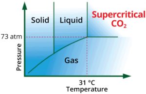
Figure 1. Critical parameters phase diagram for CO2.
SFC separations potentially can be performed at a faster rate than high-performance liquid chromatography (HPLC). The diffusion of solutes in the supercritical mobile phase can be superior to gases and exponentially larger than liquids, thereby decreasing the mass-transfer resistance in the column and allowing for rapid high-resolution separations (Table 1).
| Liquid | Supercritical fluid | Gas | |
|---|---|---|---|
| Density (g/cm3) | 1 | 0.1 to 0.5 | 10-3 |
| Viscosity (Pa•s) | 10-3 | 10-4 to 10-5 | 10-5 |
| Diffusivity (cm2/s) | 10-5 | 10-3 to 10-4 | 10-1 |
Table 1. Diffusivity of CO2, in liquid, superciritical fluid and gaseous state
A major contributing factor to the quick adoption of SFC for cannabis testing is the ability of CO2 to transition from the liquid phase into a supercritical-fluid phase at low pressures and slightly below ambient temperatures.
For reference, supercritical temperature is considered to be the temperature above the point at which a substance can no longer exist as a liquid, no matter what pressure is applied. Supercritical pressure is identified as the pressure above which a substance can no longer exist as a gas, no matter how high the temperature is raised.
Typical SFC applications run at medium pressure of 4000 psi or above and temperatures of 5°C and below. These pressure levels maintain the media in liquid form to effectively meter the fluid at a specified flow rate and retain components in the column to elute.
Supercritical fluids have lower viscosity than liquids, enabling a lower pressure drop along the column and higher efficiency with smaller particles. This decreased pressure enables a longer column to be used with a faster rate of diffusion, thus resulting in rapid analysis, compared with traditional HPLC.
At the supercritical fluid phase, CO2 also has a lower viscosity than liquid and a lower diffusivity than gas. It has higher dispersion, which enables improved efficiencies and higher optimum linear velocities than LC. All of these factors result in the following advantages compared with LC:
- faster analysis;
- decreased pressure drop across the column;
- longer column lengths;
- wider range of sensitive detectors;
- higher resolving power;
- rapid separations without using large volumes of organic solvents; and
- non-toxic mobile phase (with the exception of GCO2 and LCO2).
The primary advantage over GC is the ability of SFC to analyse non-volatile polar, highmolecular- mass samples without derivatisation at a lower vapour pressure and lower operating temperatures.
A look inside SFC equipment
In the early 2000s, SFC equipment focused on achieving higher throughput, lower cost, and higher resolution in a smaller footprint, compared with LC and GC. With the advent of new regulations for cannabis testing, many life science OEMs began to develop new SFC instrumentation with the goal of offering equipment that could test even larger sample sizes and perform at a faster rate.
SFC instrumentation consists of a solvent delivery system, an injector, a column, a pressure regulator and a data system. The latest instrumentation uses a constant-flow pump and an electronic variable restrictor, which enables the column linear velocity to decrease as the mobile phase density increases.
These developments have led to many advances in SFC, including reproducible flow-rate control and gradient delivery. Other improvements have included better pressure control, lower system dead volume and lower detector noise. The newest instrumentation accepts smaller particle size stationary phases (< 2–3 μm), and many stationary phases (that is, columns) have been produced that are specifically designed for SFC to facilitate both chiral and achiral molecule separations.
Pump mechanics
The pump is the heart of SFC equipment. Its main purpose is to maintain a precise mobile phase flow. It aids in the control of the system pressure and moves the mobile phase in a liquid state under pressure.
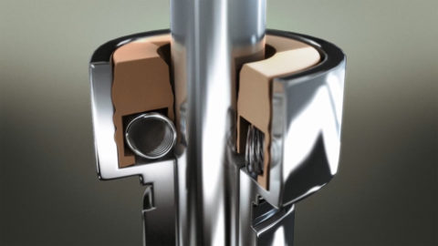
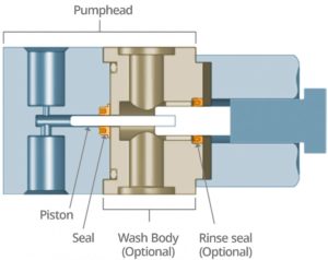 The seal is an instrumental part of the pump mechanics as it determines the life of the pump. Some SFC instrumentation includes a wash system that goes behind the pump seal to ensure lubricity when the CO2 comes into the front end of the system (Figure 2). This wash system provides a rinse cycle, which reduces seal wear, cools the system and prevents leakage at start-up. A rinse seal also can be used behind the wash body.
Some equipment also includes a refrigeration unit or insulation on the pump heads to maintain supercritical phase.
The CO2 leaves the pump solvent management delivery system, which is typically pressurised – usually from 4000 to 11 000 psi – with the plunger reciprocating to create a flow rate of 0.1–10 ml/min.
CO2 is delivered into the pump solvent management system in many different ways, including under vacuum or by introducing a chilled gas-pressurised liquid into the system. It is essential to keep the CO2 in liquid form to maximise seal performance. The set-up should be considered early in the design of the pump to minimise leakage. It is critical to ensure that the testing parameters and failure criteria are fully defined to achieve optimal pump performance and to design a seal that is appropriate for the application.
The seal plays a critical role in the pump – preventing the media from entering further into the pump mechanics or leaking out into the environment. The seal must act as a barrier, especially with CO2 being susceptible to rapid phase changes.
In a liquid–gas phase, smaller molecules could potentially pass through the sealing surfaces, because of insufficient contact sealing stresses, or through permeation of the seal jacket material. When the media comes into contact with the seal, the seal must maintain a certain amount of sealing stress to ensure proper sealing on the dynamic plunger surface as well as on the seal outer diameter (OD) to the static pump-head retaining groove.
With contact sealing stress comes friction, and if too high, the plunger speed may be reduced, resulting in pressure variations and variable flow rate, or the system could go out of sync (depending on drive mechanism), resulting in a knocking sound that indicates pump failure. If there is low contact sealing stress, then the pressure will drop immediately and the flow rate will not be held at a suitable level, causing premature failure.
Seal design
It is important to consider several factors in the design of an SFC pump. Once all of the hardware pieces are properly toleranced, alignment and performance of the pump may be affected. Tolerance stack-up between the various hardware pieces may lead to a misalignment if not properly kept in check.
Seal design, hardware design and installation procedures must all work together to prevent leakage. When designing a pump and identifying a proper seal, it is important to consider the two points summarised below.
- Determine the media phase that comes into contact with the seal. Is it liquid, vapour or a supercritical fluid?
- Determine whether the pump uses a cam or line drive motor mechanism because an effective linkage is critical to the plunger’s ability to seal friction. A cam may cost less to design in, but may have more issues with misalignment and may be more susceptible to friction.
An important design consideration is the plunger. It is essential to reduce the side load between the plunger and the pump head to prevent premature seal leakage and plunger damage. The plunger must be aligned so that there is no shaft-bore misalignment within the system itself or any side-loading to the seal that would result in a leak path during the pressure stroke.
Any misalignment can greatly affect pump performance and equipment lifetime. To maximise seal performance, the surface-finish of the plunger should be as smooth (below 4 μin RMS) and as hard (above 50 Rc) as possible to reduce abrasion and adhesion of the sealing material.
The second design consideration is plunger selection. The interaction between the seal and reciprocating plunger is one of many factors that affect seal life and proper sealing of the plunger. The material structure of the shaft can vary, and whilst sapphire is preferred, other options include ceramic or stainless steel.
Whether using a sapphire or ceramic plunger, it is important to understand the material structure in order to ensure the best performance. For sapphire, it is essential to specify crystal orientation because this will result in more consistent seal wear when riding against the sapphire material. A ceramic plunger should have a small grain size (a surface finish of less than 4 μin RMS) because large grains create greater porosity and uneven surface finishes that increase seal wear.
The next generation of seal designs must consider the challenging CO2 media phase. Both the temperature and the pressure of the media influence the performance of the seal. When designing a seal, it is important to first consider whether the phase is in a gaseous or liquid, or even supercritical state, and then to consider both the viscosity and surface tension of the media.
The pump must perform well with a liquid eluent as well as a gas solvent because sealing performance differs depending on the media phase. When in a liquid phase, CO2 has an increased density (1101 kg/m3 at saturation -37°C) and is easier to seal, whilst CO2 in the gas phase has a decreased density (1.977 kg/m3 at 1 atm and 0°C), creating a sealing challenge. CO2 reaches the liquid or supercritical phases at temperatures above 80°C and pressures above 1000 psi when it comes into contact with a seal.
Another factor that affects sealing performance is viscosity because a low-viscosity media requires increased sealing contact stress.
The seal material is dependent on the application parameters. To ensure optimal sealing performance, a dense material is needed to prevent the media from permeating through the seal. If CO2 is coming into the application in a gaseous phase, it may permeate a material that is not sufficiently dense. Seals for SFC are typically made from one of two materials: filled ultra-high molecular weight polyethylene (UHMWPE) or filled polytetrafluoroethylene (PTFE). Filled UHMWPE is often preferred in pharmaceuticals applications or in applications in which an FDA-compatible or FDA-compliant material is required.
Filled UHMWPE material is typically gold in colour and has good chemical compatibility, although it does not perform well at continuous temperatures above 80°C and at high pressures. Filled PTFE is often preferred for sealing in equipment that does not have a rinse seal component behind the high-pressure seal. PTFE has a higher temperature range and can accommodate temperatures above 204.4°C (400°F). In a controlled laboratory test, graphite- filled PTFE, which is black in colour, has the same coefficient of friction in water as does a filled UHMWPE. The downside to graphite-filled PTFE is that it is not FDA-compliant, and it can shed black particles, clogging the outlet check valve, which is not suitable for certain applications.
Polymer or polyimide-filled PTFE materials are also available for certain applications if an FDA-compliant material is required and there is minimal misalignment.
Canted coil spring energiser
The seal’s energiser design is equally important. A canted coil spring energiser is recommended when sealing small gaseous molecules as well as large-molecule liquids with low friction because it contributes to a higher amount of contact sealing stress.
The canted coil spring also ensures a constant amount of friction – minimising loads on the pump motor. The energiser material is dependent on the manufacturer’s bio-inert requirements, which may call for non-ferrous materials. For applications of 5000 psi and below, medium-force canted coil spring force energisers are generally acceptable for the liquid CO2 media phase. Higher pressure applications (> 5000 psi) may require a heavier canted coil spring to ensure that no leakage occurs at startup, particularly for applications that require the sealing of gaseous CO2.
Along with a precision aligned and guided plunger to minimise side loading onto the seal, a robust energiser enables the seal to have optimal contact stress on the dynamic lip that comes into contact with the sapphire or ceramic plunger.
A short dynamic seal ID lip provides better response to changing pressure and a sufficient preload contact stress. The long static lip on the seal’s OD is also energised, sealing within the pump-head retaining groove. It is important to ensure that there is a sufficiently high amount of contact stress to seal the OD lip to avoid any leak paths on the static surface.
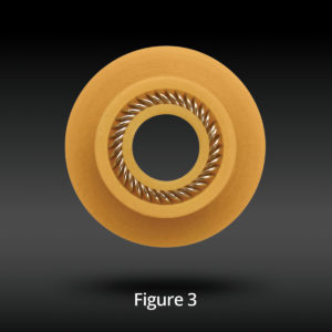
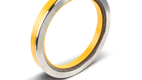
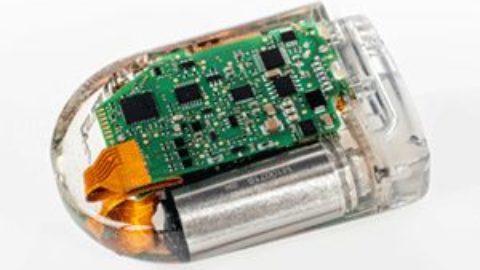
The Bal Seal reiprocating flange seal combines proven Bal Spring canted coil spring energiser technology with advanced polymer formulations. Under pressures in excess of 6000 psi and temperatures lower than 5°C, it seals consistently for more cycles to ensure better sample resolution and faster throughput in supercritical fluid chromatography.
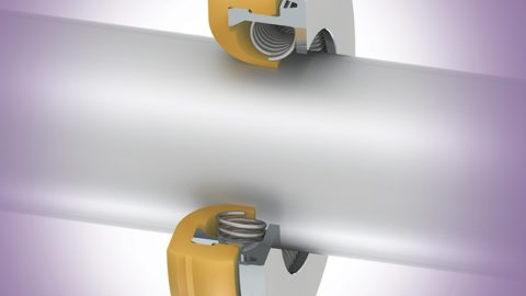
One seal design option is the flange seal (Figure 3) design for this application because it allows for two sealing surfaces whilst ensuring proper installation by compressing the flange into the pump hardware.
Design drivers
Cost, product lifetime and sealing ability are the main drivers in determining the appropriate seal for an SFC pump.
Whilst dependent on the media, pressure, temperature and other factors, the seal should perform consistently for over 1 million cycles and allow for preventative maintenance (PM) of six months to a year. Ideally, the seal design should minimise particle generation and provide consistent performance without affecting the pump’s accuracy.
Whilst equipment costs may be reduced by removing a rinse cycle, limiting seal space or not requiring a backup ring, these modifications should be considered carefully because they may affect seal performance and life.
Designing in a rinse cycle ensures lubricity to the back half of the high-pressure seal, promotes less seal wear and washes off the plunger. For high and ultra-high pressure applications, using a backup ring provides seal support to reduce material extrusion. Without a backup ring, material extrusion alters the seal design integrity, which affects sealing performance.
Conclusion
The popularity of SFC equipment for testing cannabinoids for recreational and pharmaceuticals purposes has driven the market to design instruments that provide better pressure control, lower system dead-volume and lower detector noise than ever before.
This next generation of SFC equipment has required rethinking the mechanics of the pump and developing seals that can handle the CO2 media with minimal friction for over a million of cycles. Although the design of SFC equipment may appear similar to HPLC and GC, there are small modifications and seal design enhancements that go a long way towards ensuring that the PM target can be reached consistently.
When evaluating overall pump performance, engineers often overlook the consequences of seal. Unfortunately, seals are typically the last item designed in chromatography pumps, but they are the first item reviewed after premature failure or leakage occurs.
Thermoplastic sealing is highly specialised in terms of tolerances, deflection, contact forces and physical material properties. Partnering with a sealing expert early in the design process is critical to maximising pump performance.
References
1. ‘Implementation of Achiral Supercritical Fluid Chromatography in Drug Development Testing,’ Z. Wang, et.al. posted 30 April 2013, Web: http://www.americanpharmaceuticalreview. com/Featured- Articles/135981-Implementation-of-Achiral- Supercritical-Fluid Chromatography-in- Drug-Development-Testing
2. Supercritical Fluid Extraction of Plant Flavors and Fragrances, A. Capuzzo et al., Molecules, 2013, 18, 7194-7238 (doi:10.3390/molecules18067194).
3. ‘Adopted Rules Regarding the Retail Marijuana Code (R103, R231, R234-235, R407, R604-605, R712, R1004-1004.5, R1204, R1501-1503), Adopted,’Web: https://www.colorado.gov/pacific/sites/default/filesAdopted%20Rules%20Regarding%20the%20Retail%20Marijuana%20Code%20%20%28R103,R231,R234-235,R407,R604-605,R712,R1004-1004.5,R1006-106.5,R1204,R1501-1503%29,%20Adopted%2009242014.pdf